Blog
“ics685 Unlocked: The Ultimate Guide to Acing Your Course and Boosting Your Career”
“ics685” is the cornerstone module for many Australian engineering programs, blending theory with hands‑on measurement science. If you’ve ever felt overwhelmed by the sheer amount of instrumentation, data‑acquisition, and signal‑conditioning concepts it covers, you’re not alone. In this guide we break down the curriculum, highlight the load‑cell fundamentals that under‑pin every lab, flag the common shortcuts that sabotage results, and show exactly how LoadCellShop Australia can supply the right hardware – with free technical consultation – to turn your coursework into a career‑ready skill set.
Why ics685 Is More Than Just a Course
The ics685 module (Industrial Control Systems – Instrumentation & Calibration) is deliberately interdisciplinary. It expects you to:
- Design a measurement system for force, weight, or pressure.
- Select the appropriate transducer (often a load cell).
- Calibrate and validate accuracy against industry standards.
- Integrate signal‑conditioning hardware and software for real‑time data acquisition.
Successfully mastering these steps signals to future employers that you can move from theory to production‑line reliability – a credential that dramatically improves job prospects in metals processing, mining, automation, and R&D labs across Australia.
Bottom line: If you can nail ics685, you’re already speaking the language of modern industrial instrumentation.
Understanding the Core of ics685
1. The Measurement Triangle
At its heart, ics685 teaches you to close the loop between physical quantity → transducer → digital output. The essential components are:
| Block | Typical Device | Key Specs to Track |
|---|---|---|
| Physical Quantity | Force, torque, pressure | Range, environmental exposure |
| Transducer | Load cell, pressure sensor, strain gauge | Capacity, accuracy class, material |
| Signal Conditioning | Amplifier, bridge, filter | Gain, noise rejection, excitation voltage |
| Data Acquisition | DAQ board, PLC, microcontroller | Sampling rate, resolution, interface (USB, Ethernet) |
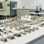
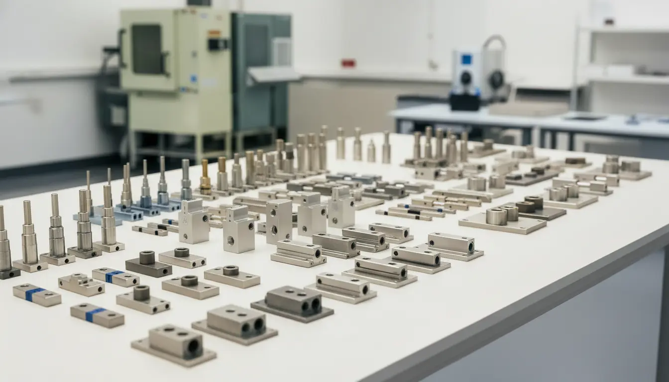
2. Load Cells – The Workhorse of Force Measurement
A load cell is a strain‑gauge transducer that converts mechanical force into an electrical voltage proportional to that force. In ics685 labs, you’ll typically encounter three configurations:
| Type | Construction | Typical Use in ics685 |
|---|---|---|
| Shear Beam | Thin, flat steel beam with four gauges (full‑bridge) | Bench‑scale calibration rigs |
| Compression (S‑type) | Two‑leg “S” shape, robust housing | Test rigs for compression testing |
| Single‑Point | Integrated under a platform, miniature | Precision weighing platforms |
Understanding the full‑bridge principle—where opposite gauges experience tension and compression—helps you interpret bridge voltage, excitation voltage, and the need for signal conditioning.
How Load Cells Fit into the ics685 Curriculum
1. Design Phase
You’ll start by defining the measurement range. For a typical lab experiment that needs to measure up to 5 kN, the rule of thumb is to select a load cell with a rated capacity 2–3× the maximum expected load (to stay within the linear region and maintain better measurement accuracy).
2. Calibration Phase
Calibration involves applying known weights (traceable to Australian National Measurement Institute standards) and recording the output voltage. The slope of the voltage‑vs‑force curve gives you the sensitivity (mV/V), while the hysteresis and non‑linearity figures dictate whether the cell meets the accuracy class required by the assignment (often Class 0.5 or Class 1).
3. Integration Phase
You’ll connect the load cell to a signal‑conditioning bridge (often a Wheatstone bridge with a 2.5 V excitation). The conditioned signal then feeds a DAQ (e.g., National Instruments or Arduino) that logs data for analysis. Proper grounding, shielded cables, and filtering are essential to avoid electrical noise that can corrupt your dataset.
4. Reporting Phase
Finally, you’ll generate a calibration report that includes uncertainty analysis, traceability statements, and recommendations for future repeatability – a document employers look for when assessing your competence in industrial instrumentation.
Where Buyers Go Wrong (and How to Avoid Costly Mistakes)
1. Choosing the Cheapest Load Cell
| Symptom | Why It Happens | Real Cost |
|---|---|---|
| Drift after a few minutes | Low‑quality strain gauges and poor temperature compensation | Re‑calibration, project delays |
| Non‑linear output | Inadequate design for the required range | Inaccurate data, failed assignment |
| Insufficient overload protection | Fragile housing | Cell damage, safety hazards |
Cheaper options fail when the lab requires high repeatability (≤ 0.1 % of full scale). When you need to demonstrate traceability to a national standard, the budget cell simply won’t give you a credible calibration curve.
2. Ignoring Material Compatibility
If you’re measuring corrosive chemicals or high‑humidity environments, a standard stainless‑steel cell can corrode, leading to zero‑shift and eventual failure. Use stainless‑steel (316L) or aluminum housings where appropriate.
3. Not Matching the Accuracy Class to the Assignment
Some labs only require Class 2 accuracy, but if you inadvertently select a Class 0.2 cell, you may over‑pay without real benefit. Conversely, picking a Class 2 cell for a high‑precision weighing experiment will cause your marks to suffer.
4. Over‑loading the Cell During Setup
Even a robust cell has a rated overload limit (often 150 % of capacity). Exceeding this can permanently deform the strain gauges, rendering the cell useless.
5. Skipping Signal‑Conditioning Evaluation
A raw bridge output of a few mV is too low for most DAQs. Failing to pair the cell with a proper instrumentation amplifier leads to noisy data and failed experiments.
When Cheaper Options Fail – Real‑World Examples
| Scenario | Cheap Cell Used | Outcome |
|---|---|---|
| Student project: 2 kN compression test | 2 kN shear beam, $120 | Cell overloaded at 2.3 kN → permanent damage; project halted |
| Research lab: High‑precision weighing (0.01 g repeatability) | Single‑point cell, $85 | Non‑linearity > 2 % → data rejected by supervisor |
| Industrial internship: Monitoring pneumatic cylinder force | Aluminum S‑type, $95 | Temperature drift > 0.5 % in a 30 °C swing -> calibration drift daily |
The pattern is clear: short‑term savings turn into long‑term setbacks. Investing in a reputable supplier that offers technical support and customisation prevents these pitfalls.
When NOT to Use Certain Products
| Product Type | Unsuitable For | Reason |
|---|---|---|
| Single‑Point Miniature Load Cells | High‑load (> 10 kN) compression rigs | Limited capacity, non‑linear response at high forces |
| Low‑Cost Aluminum S‑type Cells | Corrosive or high‑temperature environments | Poor corrosion resistance, drift with heat |
| Non‑rated (Un‑certified) Load Cells | Calibration labs requiring NMI traceability | No documented accuracy class, no certificate of calibration |
If you’re unsure, always ask a specialist – LoadCellShop Australia offers free consultation to match the exact transducer to your specific application.
Selecting the Right Load Cell for Your ics685 Lab
Below is a concise product recommendation table featuring models that balance price, accuracy, and durability for typical ics685 experiments. All items are stocked at LoadCellShop Australia and can be shipped nationwide.
| # | Model | Capacity | Accuracy Class | Material | Typical Application | Approx. Price (AUD) | SKU |
|---|---|---|---|---|---|---|---|
| 1 | SCS‑5K‑B | 5 kN | Class 0.5 | Stainless‑steel (316) | Shear‑beam bench scale, overload testing | $345 | SCS5K‑B |
| 2 | SC‑2K‑S | 2 kN | Class 1 | Aluminum (6061) | S‑type compression rigs, low‑cost prototyping | $210 | SC2K‑S |
| 3 | SP‑500‑P | 500 g | Class 0.2 | Stainless‑steel (304) | Single‑point precision weighing, lab balances | $180 | SP500‑P |
| 4 | CUSTOM‑10K‑ST | 10 kN (custom) | Class 0.2 (custom) | Stainless‑steel (316L) | High‑force testing, mining equipment R&D | $720 (incl. customisation) | C10K‑ST |
| 5 | HD‑1K‑F | 1 kN | Class 2 | Cast iron | Heavy‑duty floor‑mounted force measurement (non‑critical) | $150 | HD1K‑F |
Why Each Model Is Suitable
- SCS‑5K‑B – The stainless‑steel shear beam provides excellent repeatability (≤ 0.08 % FS) and a low hysteresis (< 0.02 % FS). Ideal for any ics685 lab that demands Class 0.5 accuracy across a 5 kN range.
- SC‑2K‑S – Offers a cost‑effective solution for low‑force compression tests where Class 1 is acceptable. Its aluminum housing keeps weight low for portable rigs.
- SP‑500‑P – A single‑point cell with Class 0.2 accuracy, perfect for high‑precision weighing platforms often used in final-year projects.
- CUSTOM‑10K‑ST – When off‑the‑shelf capacity isn’t enough, the custom option can be built to exact specifications (including special sealing for dusty mines).
- HD‑1K‑F – A Class 2 floor‑mounted cell; good for teaching basic concepts where ultra‑high accuracy isn’t required.
When a Model Is NOT Ideal
| Model | Not Ideal For | Better Alternative |
|---|---|---|
| SCS‑5K‑B | Sub‑gram weighing | SP‑500‑P (higher resolution) |
| SC‑2K‑S | High‑temperature (> 80 °C) environments | Custom‑10K‑ST with heat‑treated housing |
| SP‑500‑P | Loads > 1 kN | SCS‑5K‑B (higher capacity) |
| CUSTOM‑10K‑ST | Tight budget projects | SCS‑5K‑B (standard) |
| HD‑1K‑F | Precision calibration labs | SCS‑5K‑B (better accuracy) |
All models ship with certified calibration certificates and can be paired with signal‑conditioning modules from our store to complete the measurement chain.
Step‑by‑Step Guide to Integrating a Load Cell into Your ics685 Lab Setup
- Define the Measurement Requirements
- Determine the maximum force, desired accuracy, and environmental conditions.
- Select the Appropriate Load Cell (refer to table above).
- Mount the Cell Correctly
- Use graded bolts (M5 or M6) with appropriate torque (typically 2 Nm for 5 kN cell). Avoid over‑tightening – it introduces pre‑load error.
- Wire the Full‑Bridge
- Connect the four gauge leads to the bridge terminals (+, –, +, –). Use shielded twisted‑pair cable (e.g., Belden 8723) to minimise noise.
- Supply Excitation Voltage
- Most ics685 labs use 2.5 V ± 0.1 V DC from a precision power supply. Verify polarity.
- Add Signal Conditioning
- Insert an instrumentation amplifier (e.g., AD620) with a gain set to output 0‑5 V for the expected force range. Include a low‑pass filter (cut‑off 500 Hz) to suppress high‑frequency interference.
- Connect to Data Acquisition (DAQ)
- Use a USB DAQ with 16‑bit resolution (minimum) and a sampling rate of ≥ 1 kS/s for dynamic tests.
- Perform a Two‑Point Calibration
- Apply a zero load and a known reference weight (e.g., 2 kN). Record the output voltages, calculate sensitivity (mV/V).
- Validate Linearity and Hysteresis
- Incrementally load up to 100 % of capacity, then unload, recording data at each step. Plot the curve to check that deviation stays within the accuracy class.
- Document the Calibration
- Generate a PDF report with uncertainty budget, traceability notes, and next calibration due date (usually 12 months).
Following these steps ensures that the measurement system you build for ics685 meets both academic grading criteria and industry‑standard best practice.
Comparison: Off‑the‑Shelf vs Custom Load Cells for ics685 Projects
| Feature | Off‑the‑Shelf Load Cell | Custom‑Engineered Load Cell |
|---|---|---|
| Lead Time | 2–5 business days (stock) | 3–6 weeks (design & build) |
| Cost | Lower (AUD 150‑350) | Higher (AUD 500‑800) |
| Tailored Capacity | Fixed (standard ranges) | Exact capacity, overload rating |
| Material/Finish Options | Standard stainless/Aluminum | Specialized alloys, IP‑rating, explosion‑proof |
| Calibration Certificate | Generic (Class 1‑2) | Full NMI‑traceable (any class) |
| Ideal For | Teaching labs, prototype rigs | High‑precision R&D, harsh environment tests |
For most university labs the off‑the‑shelf options (SCS‑5K‑B, SC‑2K‑S) are sufficient. For industry‑linked capstone projects requiring stringent traceability, a custom solution from LoadCellShop Australia may be the better route.
Mistakes to Avoid When Specifying Load Cells for ics685
- Mis‑reading the Capacity Rating – A 2 kN cell does not mean you can safely apply 2 kN repeatedly; aim for a 30 % safety margin.
- Neglecting Temperature Compensation – Many students forget to check the TC (Temperature Coefficient); a 0.02 %/°C drift can become a 200 g error at 20 °C change.
- Using Unshielded Cables – This invites EMI from nearby motors or Wi‑Fi routers, corrupting the low‑level bridge signal.
- Skipping Ground Loops Checks – A single‑point ground at the DAQ without proper isolation can cause offset drift.
- Assuming All Load Cells Are Interchangeable – Physical mounting geometry and bridge wiring polarity differ; swapping blades without rewiring leads to reversed output signs.
How LoadCellShop Australia Helps You Succeed in ics685
- Free Technical Consultation – Our engineers review your project brief, suggest the optimal cell, and outline the required signal‑conditioning accessories.
- End‑to‑End Solutions – From load cell to amplifier, cabling, and DAQ we supply a complete kit that’s already matched to your specifications.
- Custom Cell Design – If your assignment demands a non‑standard size or special coating (e.g., marine‑grade 316L), we can engineer it to your exact needs.
- Bulk‑Order Discounts – Get 5 % off when you order three or more cells – perfect for labs that need multiple units for parallel testing.
- Local Support – Based at Unit 27/191 McCredie Road, Smithfield NSW 2164, we provide fast shipping across Australia and a dedicated contact (Phone +61 4415 9165, Email sales@sandsindustries.com.au).
Pro tip: Bookmark our shop page (http://www.loadcellsolutions.com.au/shop) and add your shortlisted models to a Wish List – our sales team can then prepare a quote with calibration certificates ready for your professor’s approval.
Frequently Asked Questions (FAQs)
| Question | Answer |
|---|---|
| Do I need a separate power supply for the load cell? | Yes. Most bridge circuits require a stable DC excitation (2.5 V to 10 V). An unstable supply introduces gain errors. |
| Can I use a load cell with a microcontroller (Arduino) for the lab? | Absolutely, but you’ll need an instrumentation amplifier (e.g., HX711) and proper filtering to achieve reliable readings. |
| What is the difference between Class 0.2 and Class 0.5 accuracy? | Class 0.2 means the maximum error is 0.2 % of full scale, whereas Class 0.5 allows up to 0.5 % error. Choose based on your assignment’s tolerance. |
| Is calibration required every time I change the load cell? | Yes. Even cells of the same model can have slightly different zero offsets; a quick two‑point check is good practice. |
| Do you ship internationally? | Currently we focus on Australian customers, but we can arrange export to nearby regions on request. |
The Bigger Picture: Leveraging ics685 Skills for Your Career
When you master load‑cell integration, calibration, and data‑analysis in ics685, you unlock a suite of high‑demand capabilities:
| Skill | Industry Relevance |
|---|---|
| Force measurement & testing | Mining equipment verification, aerospace structural testing |
| Signal conditioning design | Automation PLC integration, IoT sensor networks |
| Calibration & traceability | Metrology labs, NMI‑linked quality assurance |
| Data acquisition & analysis | Process control, predictive maintenance algorithms |
| Project documentation | Engineering change orders, compliance dossiers |
Australian firms such as BHP, Orica, and Thales actively recruit graduates who can design reliable measurement systems. Position yourself as a problem‑solver rather than just a lab technician – your ics685 portfolio becomes a living showcase of competence.
Conclusion
Mastering ics685 is a decisive step toward a thriving engineering career, and the right load‑cell hardware is the backbone of every successful lab experiment. By avoiding cheap, ill‑suited transducers, respecting accuracy classes, and following systematic integration procedures, you’ll consistently deliver data that meets both academic and industry standards.
LoadCellShop Australia is ready to be your trusted partner in this journey. Whether you need a standard shear‑beam cell, a custom‑engineered solution, or simply a free consultation to confirm the best choice for your project, our team of experienced specialists is just a call or email away.
Ready to power up your ics685 lab? Visit our Contact page (http://www.loadcellsolutions.com.au/our-contacts/) or explore the full range of load cells in our Shop (http://www.loadcellsolutions.com.au/shop) and let us help you turn theory into precision‑measured practice.
LoadCellShop Australia – Your One‑Stop Destination for Load Cells, Calibration Services, and Expert Advice
Address: Unit 27/191 McCredie Road, Smithfield NSW 2164, Australia
Phone: +61 4415 9165 | +61 477 123 699
Email: sales@sandsindustries.com.au
Website: http://www.loadcellsolutions.com.au